
Structure Design of Special Picking Manipulators
The manipulator can make the assembly line production more efficient and automatic. As an automatic production tool, it can replace people's manual labor, greatly improve the production efficiency of the injection molding machines, and its production environment is safe and the product quality is stable. In recent years, the number of domestic enterprises engaged in the production of plastic parts picking manipulators is very rare, with weak originality and over-reliance on imitation. A large number of products are imported from other countries, but their design ideas are more western, which is not suitable for Chinese people's operating habits. Therefore, it is necessary for us to design and produce a high-efficiency, low-cost and stable mechanical hand for plastic parts.
Design content
When a new injection product is finished, it will be automatically pushed to the conveyor belt by the machine, and the manipulator will constantly pick up the plastic parts from the conveyor belt and place them in the designated plastic parts stacking area. The designed manipulator (as shown in Figure 1) is driven by air pressure and has five moving units, and each moving unit moves according to the design requirements in the form of the air cylinder. The design focus of this manipulator is to complete the structural design of the manipulator for making plastic parts.
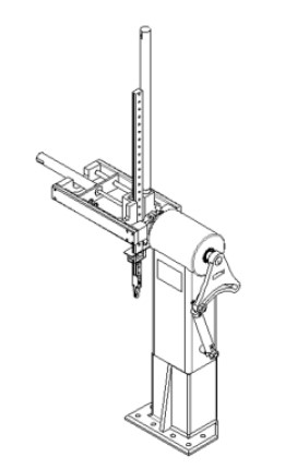
Figure 1 Manipulator
Structural scheme design of the manipulator
The designed manipulator is specially designed for the injection molding machine, so the size and movement stroke of the manipulator should match the injection molding machine, and the working progress of the injection molding machine should be met. The working rhythm of the injection molding machine is relatively fast, and the speed of completing a product is very fast, so it is necessary for the manipulator to grab the plastic parts quickly and accurately, and then it is necessary to place the plastic parts to the corresponding positions in sequence and return quickly at the same time. The whole time should be compared with the unit time of the injection molding machine to produce a product. The shape and size of the injection molding machine should also be considered when designing a special manipulator. First, ensure that the manipulator has enough operation space; The second is to make the design of the manipulator more specific and efficient.
1) selection of coordinate type and degree of freedom. The designed manipulator needs to ascend and descend, move back and forth, loosen parts and rotate hands. In order to save space and shorten the movement stroke, the degree of freedom of an arm swinging back and forth is increased. According to these five degrees of freedom, the coordinate form of the manipulator is determined as a cylindrical coordinate. The kinematic diagram of each degree of freedom of the manipulator is shown in Figure 2.
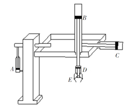
Figure 2 Schematic diagram of each degree of freedom
2) Main parameters of manipulator. Injection molding machines are usually used in single batch production. According to the functional parameters of common injection molding machines, the motion limit parameters of each degree of freedom are designed: the maximum grasping mass of the manipulator hand (3 kg) is the working limit value of the manipulator 3kg; The rotation angle of the manipulator is 90; The maximum working stroke of the manipulator to move up and down in a straight line is 800mm; The part outside the robot body realizes reciprocating rocking motion, and the motion limit angle is 180; The manipulator arm can move back and forth on the working plane, and the maximum working stroke is 400 mm.
Hand structure design
The hand structure is claw type, as shown in Figure 3. When the nozzle clamp needs to grab an object, the air inlet of the air cylinder pushes the piston rod to move, and the conical pin pushes the roller to both sides. The roller is connected with the left and right clamp plates, and the roller directly controls the opening and closing of the clamp plates, so as to grab the plastic parts. When the plastic parts are put down, the air cylinder is cut off directly, and the clamp plates will be reset under the action of the reset spring, thus achieving the purpose of releasing the plastic parts. The model of nozzle clamp selected in this paper is 1615s, which can grab 500 g plastic parts at most. The cylinder diameter of the nozzle is 16 mm and the stroke is 15 mm.
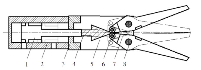
Fig. 3 Structure of nozzle clamp
1. Install cylinder 2, connecting seat 3, conical pin 4, roller 5, pin 6, and reset.
7. Spring, left clamp plate 8. Right clamp plate
Part of wrist structure design
Just like the human body structure, the connecting part between the hand and arm of the manipulator is also the wrist, which plays an important role. The flexibility of the wrist can make the finishing touch. Generally, the wrist can be used to change the direction of a grasping part of the manipulator's hand, so the wrist part is also designed with a degree of freedom, and the movement form is rotation. The nozzle clamp and rotary cylinder are used as a component, and the cooperation between the hand (i.e. nozzle clamp) and the wrist (rotary cylinder) of the manipulator is shown in Figure 4.
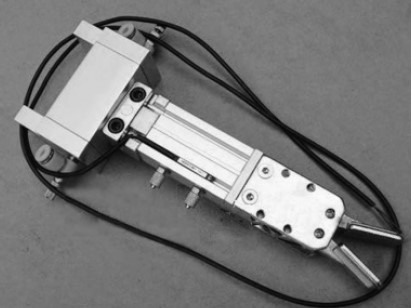
Fig. 4 Combined components of the rotary cylinder of nozzle clamp
Auxiliary arm structure design
1. Structure design of auxiliary arm
The designed manipulator arm chooses the aluminum profile as the main material, and in the structure, by combining the arm with the moving guide rail, the weight is reduced and the structural difficulty is reduced. Choice of guide rail: The degree of freedom of the auxiliary arm is its linear movement up and down, so its attachment support can choose the form of the linear guide rail. The design adopts a ball linear guide rail, and the physical object is shown in Figure 5.
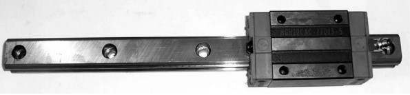
Figure 5 Ball linear guide rail
The silver linear guide rail is adopted in the design, and the selected model is HG. The total mass of the slider matched with it is 0.9 kg.
2. Structural dimensions of the auxiliary arm cylinder
The cylinder selected in this paper is CG linear cylinder produced by SMC Company, and its radius is 20 mm. The stroke of the arm cylinder is 800mm, as shown in Figure 6.
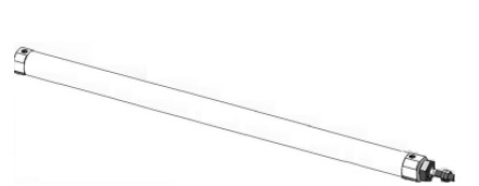
Fig. 6 auxiliary arm cylinder
3. Design of the connection structure between wrist and arm.
1) Selection of connecting form of auxiliary arm cylinder. Under the action of the manipulator, the auxiliary arm cylinder pushes the guide rail to reciprocate linearly. In this case, there is no relative movement between the piston rod of the cylinder and the guide rail of the auxiliary arm, that is to say, it needs to be relatively fixed. It is best to choose the form of rod end nut, as shown in Figure 7.
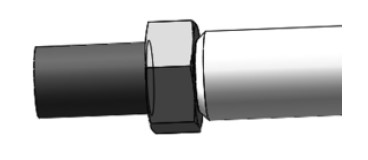
Fig. 7 Structure of rod end nut
2) Design of the connection structure between wrist and auxiliary arm. The wrist is a rotary cylinder, while the auxiliary arm is a guide rail-based structure. There is no calibrated connection between them, so it is necessary to design a connecting part to connect the wrist and the auxiliary arm together. In addition to connecting the rotary cylinder and the guide rail, the connector also needs to connect the piston rod of the auxiliary arm cylinder, which is the connection method of the rod end nut of the piston. The final design scheme is shown in Figure 8.
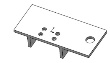
Fig. 8 connector
Structural design of manipulator main arm
1. Structural design of the main arm
Aluminum alloy is selected as the main material of the main arm structure, which is relatively light, can bear a large load and has good mechanical properties. The structure of the main arm is shown in Figure 9. Like the force of the auxiliary arm, the main arm is supported and guided by two guide rods, so that the force is more uniform, the guidance is better, and the symmetry is good. According to the design size of the main arm, the length of the guide rod can be 460-470 mm In this paper, an intermediate value of 465 mm with a diameter of 20 mm is selected, as shown in Figure 10.
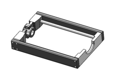
Fig. 9 General Design Diagram of Main Arm
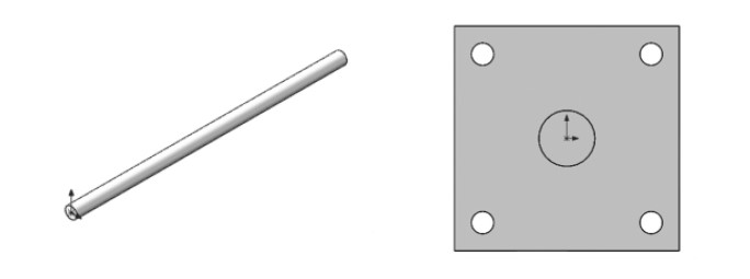
Fig. 10 Guide rod
Fig. 11 Axial foot seat
2. Design of connecting structure of the main arm and auxiliary arm
1) Selection of connecting form of main arm cylinder. Combined with the use requirements of the main arm cylinder, the axial foot seat is finally selected to fix the main arm cylinder. As shown in Figure 11.
2) Design of the connection structure between the auxiliary arm and the main arm. The main arm and the auxiliary arm need to design a component to connect with each other. This part needs to connect the auxiliary arm slider, the cylinder piston rod of the main arm, two guide rods, etc. Therefore, the whole structure needs to first determine the connection position and connection mode of each component, all of which are connected by bolts. The final structure is shown in Figure 12, and this component is also made of aluminum alloy.
The structure design of the fuselage
1. The overall design of the fuselage
The last degree of freedom of the manipulator can achieve a swinging movement with a swinging stroke of 90. The machine body is used as a bearing component, and a reasonable structure is designed to achieve this degree of freedom. The corresponding machine body structure can be designed as shown in Figure 13. For the sake of economy and practicality, GY-4590 material is used in the body of the manipulator, which is moderately priced but widely used.
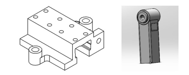
Fig. 12 connecting parts
Figure 13 Three-dimensional view of the fuselage
2. Design of the connection structure between the fuselage and the main arm
The robot body needs to support all parts of the robot except itself, such as the hand, wrist, main arm, auxiliary arm and other accessory structures, so the force on the robot body is the largest in the whole robot structure. It is designed to be a shaft-shaped part connected with the main arm of the fuselage. As the connecting part bears a large pressure, it is also subjected to a large torque and bending moment. The material of this part is 45 steel, and the parameter of the connecting shaft is 435 cm×45 cm. The structure is shown in Figure 14. The two ends of the shaft are respectively connected with the rocker mechanism and the main arm mechanism, and both ends are fixed by bolts so that no relative movement can occur between any two, otherwise, the design will be invalid directly, and the assembly will be simulated through three-dimensional modeling.

Fig. 14 connecting shaft
3. Selection of airframe cylinder and calculation of driving torque
Due to the limitation of structure, the fuselage cylinder also needs to be designed as a linear cylinder, and the swing drive can be realized through the conversion of certain mechanisms. The cylinder designed here is still a CG1 double-acting single piston rod cylinder, and the radius of the linear cylinder is 20 mm.
1) Connecting knot of fuselage cylinder
Structure design. Because the airframe cylinder needs to convert the linear motion of the cylinder into the swinging motion, the degree of freedom of the cylinder block cannot be completely limited. Because linear motion is converted into swing, it is required that the cylinder block can also make a certain amount of relative rotation. Otherwise, the dead point position in the linkage mechanism will appear, which will lead to the failure of the device and the inability to realize adjustability. The whole conversion mechanism designed is shown in Figure 15.
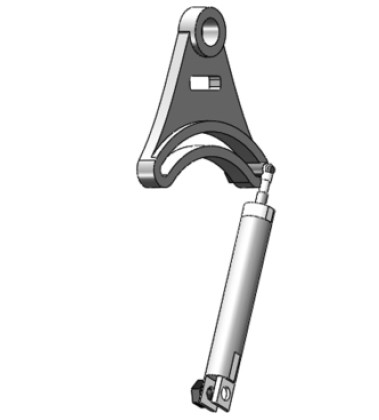
Fig. 15 linear cylinder motion conversion mechanism
2) Buffer design. The five degrees of freedom of the whole manipulator are driven by air cylinders, and the characteristics of air cylinders lead to large inertia in operation. Except for the rotary air cylinder with its wrist in the nozzle of the hand and the linear air cylinder swing mechanism of the fuselage, there is no need to design a buffer device, and the other two air cylinders need to be designed with buffer devices, which can ensure the reliability of the system and protect the components. The size and structure of the manipulator for taking plastic parts are not big, and the relative inertia will not be large, so the design requirements can be met by using the hydraulic buffer. The structure of the hydraulic buffer is shown in Figure 16.
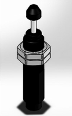
Figure 16 Buffer
Conclusion
The designed manipulator is applied to streamline the injection molding machine in the injection molding industry and is specially used to grab plastic parts. A total of five degrees of freedom are designed for the manipulator, and the movement is realized by the cylinder. Except that the wrist cylinder is a rotary cylinder, the other four cylinders are linear cylinders. The manipulator has high working efficiency, low cost and stable performance.
Design content
When a new injection product is finished, it will be automatically pushed to the conveyor belt by the machine, and the manipulator will constantly pick up the plastic parts from the conveyor belt and place them in the designated plastic parts stacking area. The designed manipulator (as shown in Figure 1) is driven by air pressure and has five moving units, and each moving unit moves according to the design requirements in the form of the air cylinder. The design focus of this manipulator is to complete the structural design of the manipulator for making plastic parts.
Figure 1 Manipulator
Structural scheme design of the manipulator
The designed manipulator is specially designed for the injection molding machine, so the size and movement stroke of the manipulator should match the injection molding machine, and the working progress of the injection molding machine should be met. The working rhythm of the injection molding machine is relatively fast, and the speed of completing a product is very fast, so it is necessary for the manipulator to grab the plastic parts quickly and accurately, and then it is necessary to place the plastic parts to the corresponding positions in sequence and return quickly at the same time. The whole time should be compared with the unit time of the injection molding machine to produce a product. The shape and size of the injection molding machine should also be considered when designing a special manipulator. First, ensure that the manipulator has enough operation space; The second is to make the design of the manipulator more specific and efficient.
1) selection of coordinate type and degree of freedom. The designed manipulator needs to ascend and descend, move back and forth, loosen parts and rotate hands. In order to save space and shorten the movement stroke, the degree of freedom of an arm swinging back and forth is increased. According to these five degrees of freedom, the coordinate form of the manipulator is determined as a cylindrical coordinate. The kinematic diagram of each degree of freedom of the manipulator is shown in Figure 2.
Figure 2 Schematic diagram of each degree of freedom
2) Main parameters of manipulator. Injection molding machines are usually used in single batch production. According to the functional parameters of common injection molding machines, the motion limit parameters of each degree of freedom are designed: the maximum grasping mass of the manipulator hand (3 kg) is the working limit value of the manipulator 3kg; The rotation angle of the manipulator is 90; The maximum working stroke of the manipulator to move up and down in a straight line is 800mm; The part outside the robot body realizes reciprocating rocking motion, and the motion limit angle is 180; The manipulator arm can move back and forth on the working plane, and the maximum working stroke is 400 mm.
Hand structure design
The hand structure is claw type, as shown in Figure 3. When the nozzle clamp needs to grab an object, the air inlet of the air cylinder pushes the piston rod to move, and the conical pin pushes the roller to both sides. The roller is connected with the left and right clamp plates, and the roller directly controls the opening and closing of the clamp plates, so as to grab the plastic parts. When the plastic parts are put down, the air cylinder is cut off directly, and the clamp plates will be reset under the action of the reset spring, thus achieving the purpose of releasing the plastic parts. The model of nozzle clamp selected in this paper is 1615s, which can grab 500 g plastic parts at most. The cylinder diameter of the nozzle is 16 mm and the stroke is 15 mm.
Fig. 3 Structure of nozzle clamp
1. Install cylinder 2, connecting seat 3, conical pin 4, roller 5, pin 6, and reset.
7. Spring, left clamp plate 8. Right clamp plate
Part of wrist structure design
Just like the human body structure, the connecting part between the hand and arm of the manipulator is also the wrist, which plays an important role. The flexibility of the wrist can make the finishing touch. Generally, the wrist can be used to change the direction of a grasping part of the manipulator's hand, so the wrist part is also designed with a degree of freedom, and the movement form is rotation. The nozzle clamp and rotary cylinder are used as a component, and the cooperation between the hand (i.e. nozzle clamp) and the wrist (rotary cylinder) of the manipulator is shown in Figure 4.
Fig. 4 Combined components of the rotary cylinder of nozzle clamp
Auxiliary arm structure design
1. Structure design of auxiliary arm
The designed manipulator arm chooses the aluminum profile as the main material, and in the structure, by combining the arm with the moving guide rail, the weight is reduced and the structural difficulty is reduced. Choice of guide rail: The degree of freedom of the auxiliary arm is its linear movement up and down, so its attachment support can choose the form of the linear guide rail. The design adopts a ball linear guide rail, and the physical object is shown in Figure 5.
Figure 5 Ball linear guide rail
The silver linear guide rail is adopted in the design, and the selected model is HG. The total mass of the slider matched with it is 0.9 kg.
2. Structural dimensions of the auxiliary arm cylinder
The cylinder selected in this paper is CG linear cylinder produced by SMC Company, and its radius is 20 mm. The stroke of the arm cylinder is 800mm, as shown in Figure 6.
Fig. 6 auxiliary arm cylinder
3. Design of the connection structure between wrist and arm.
1) Selection of connecting form of auxiliary arm cylinder. Under the action of the manipulator, the auxiliary arm cylinder pushes the guide rail to reciprocate linearly. In this case, there is no relative movement between the piston rod of the cylinder and the guide rail of the auxiliary arm, that is to say, it needs to be relatively fixed. It is best to choose the form of rod end nut, as shown in Figure 7.
Fig. 7 Structure of rod end nut
2) Design of the connection structure between wrist and auxiliary arm. The wrist is a rotary cylinder, while the auxiliary arm is a guide rail-based structure. There is no calibrated connection between them, so it is necessary to design a connecting part to connect the wrist and the auxiliary arm together. In addition to connecting the rotary cylinder and the guide rail, the connector also needs to connect the piston rod of the auxiliary arm cylinder, which is the connection method of the rod end nut of the piston. The final design scheme is shown in Figure 8.
Fig. 8 connector
Structural design of manipulator main arm
1. Structural design of the main arm
Aluminum alloy is selected as the main material of the main arm structure, which is relatively light, can bear a large load and has good mechanical properties. The structure of the main arm is shown in Figure 9. Like the force of the auxiliary arm, the main arm is supported and guided by two guide rods, so that the force is more uniform, the guidance is better, and the symmetry is good. According to the design size of the main arm, the length of the guide rod can be 460-470 mm In this paper, an intermediate value of 465 mm with a diameter of 20 mm is selected, as shown in Figure 10.
Fig. 9 General Design Diagram of Main Arm
Fig. 10 Guide rod
Fig. 11 Axial foot seat
2. Design of connecting structure of the main arm and auxiliary arm
1) Selection of connecting form of main arm cylinder. Combined with the use requirements of the main arm cylinder, the axial foot seat is finally selected to fix the main arm cylinder. As shown in Figure 11.
2) Design of the connection structure between the auxiliary arm and the main arm. The main arm and the auxiliary arm need to design a component to connect with each other. This part needs to connect the auxiliary arm slider, the cylinder piston rod of the main arm, two guide rods, etc. Therefore, the whole structure needs to first determine the connection position and connection mode of each component, all of which are connected by bolts. The final structure is shown in Figure 12, and this component is also made of aluminum alloy.
The structure design of the fuselage
1. The overall design of the fuselage
The last degree of freedom of the manipulator can achieve a swinging movement with a swinging stroke of 90. The machine body is used as a bearing component, and a reasonable structure is designed to achieve this degree of freedom. The corresponding machine body structure can be designed as shown in Figure 13. For the sake of economy and practicality, GY-4590 material is used in the body of the manipulator, which is moderately priced but widely used.
Fig. 12 connecting parts
Figure 13 Three-dimensional view of the fuselage
2. Design of the connection structure between the fuselage and the main arm
The robot body needs to support all parts of the robot except itself, such as the hand, wrist, main arm, auxiliary arm and other accessory structures, so the force on the robot body is the largest in the whole robot structure. It is designed to be a shaft-shaped part connected with the main arm of the fuselage. As the connecting part bears a large pressure, it is also subjected to a large torque and bending moment. The material of this part is 45 steel, and the parameter of the connecting shaft is 435 cm×45 cm. The structure is shown in Figure 14. The two ends of the shaft are respectively connected with the rocker mechanism and the main arm mechanism, and both ends are fixed by bolts so that no relative movement can occur between any two, otherwise, the design will be invalid directly, and the assembly will be simulated through three-dimensional modeling.
Fig. 14 connecting shaft
3. Selection of airframe cylinder and calculation of driving torque
Due to the limitation of structure, the fuselage cylinder also needs to be designed as a linear cylinder, and the swing drive can be realized through the conversion of certain mechanisms. The cylinder designed here is still a CG1 double-acting single piston rod cylinder, and the radius of the linear cylinder is 20 mm.
1) Connecting knot of fuselage cylinder
Structure design. Because the airframe cylinder needs to convert the linear motion of the cylinder into the swinging motion, the degree of freedom of the cylinder block cannot be completely limited. Because linear motion is converted into swing, it is required that the cylinder block can also make a certain amount of relative rotation. Otherwise, the dead point position in the linkage mechanism will appear, which will lead to the failure of the device and the inability to realize adjustability. The whole conversion mechanism designed is shown in Figure 15.
Fig. 15 linear cylinder motion conversion mechanism
2) Buffer design. The five degrees of freedom of the whole manipulator are driven by air cylinders, and the characteristics of air cylinders lead to large inertia in operation. Except for the rotary air cylinder with its wrist in the nozzle of the hand and the linear air cylinder swing mechanism of the fuselage, there is no need to design a buffer device, and the other two air cylinders need to be designed with buffer devices, which can ensure the reliability of the system and protect the components. The size and structure of the manipulator for taking plastic parts are not big, and the relative inertia will not be large, so the design requirements can be met by using the hydraulic buffer. The structure of the hydraulic buffer is shown in Figure 16.
Figure 16 Buffer
Conclusion
The designed manipulator is applied to streamline the injection molding machine in the injection molding industry and is specially used to grab plastic parts. A total of five degrees of freedom are designed for the manipulator, and the movement is realized by the cylinder. Except that the wrist cylinder is a rotary cylinder, the other four cylinders are linear cylinders. The manipulator has high working efficiency, low cost and stable performance.
