
Servo Control System for Robot Injection Molding Machines
With the development of 3C control technology and the increasing labor cost, the intelligent automatic control of mechanical equipment becomes more and more important. A three-axis servo manipulator for the injection molding machine is designed, which includes the design and manufacture of hardware circuits and software programming, and a man-machine interface based on the Devin touch screen is designed. Field tests show that the manipulator is safe, stable, convenient and efficient, and has a strong anti-interference ability.
Hardware design of injection molding machine control system
1. Overall design
The overall design of the control system is shown in Figure 1.
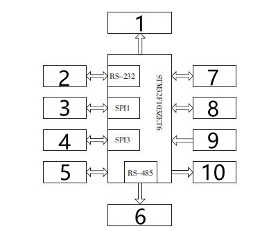
Fig. 1 overall design block diagram
1. Power supply module 2. Devin DGUS 3. Memory W25X16 4. U disk 5.RJ45 network port 6.I/O extended version 7. Injection molding machine 8. Servo system 9. Signal detection 10. Alarm.
2. Power supply module
Under normal circumstances, the servo motor needs a 24V power supply, the main control chip needs a 3.3V power supply, and the common optocoupler needs a 5V power supply. Therefore, the manipulator control board needs a power conversion circuit to reduce 24V to 5V and 5V to 3.3V The 24V to 5V circuit adopts the VRB2405YMD chip, which has an isolation function. It inputs a wide DC voltage of 18-75V, stably outputs 5V, and the maximum output current is 1.2A The circuit from 5V to 3.3V adopts linear voltage stabilizing chip AMS1117-3.3, and the input voltage is 4.7-12V.
From 24V to 5V, because the voltage input of the power supply module is limited, it will not work normally when the input voltage is lower than the lowest voltage of 18V, so the system needs to design a low-voltage detection module.
3. I/O port circuit
I/O input and output circuits mainly include:
(1) Optocoupler isolation circuit. All I/O ports are isolated by optocoupler to protect the main control board, and most of the isolation circuits in the design adopt EL817 optocoupler.
(2) Expand the I/O circuit. As the system needs more ports, under the condition that it can't meet the requirements, the design adopts an extended way, and 74HC164 and 74HC595 are selected.
(3) Relay controls the input and output circuit.
(4) Alarm output circuit, as shown in Figure 2.
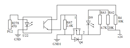
Figure 2 Alarm circuit
(5) Pulse output interface circuit. The servo motor is controlled by pulse, which is first isolated and output by high-speed optocoupler A2631, and then
Then the pulse is output differentially through AM26LS31.
4. Communication port circuit, Flash memory circuit, network port and emergency stop circuit.
(1)RS-485 circuit
RS-485 communication is adopted, and the circuit is shown in Figure 3. Its anti-common mode interference ability is strong, the maximum transmission distance can reach 1200m, and the maximum number of interfaces can be mounted at 128.
(2) RS-232 circuit
To ensure the data is not lost, asynchronous communication is adopted, and the SP3232EEN chip is selected, which can provide bidirectional communication at the same time. The circuit schematic diagram is shown in Figure 4.
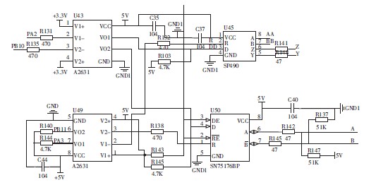
Figure 3 RS-485 communication interface
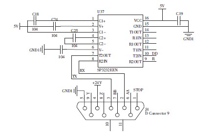
Figure 4 RS-232 Module
(3) USB communication circuit
In order to simplify the design, the USB chip CH376 with a file management system is adopted, which supports the SPI interface to operate the U disk. In the system, the U disk can be used to copy programs conveniently, and the chip needs five I/O ports.
(4) Flash circuit
Because the system needs to save the teaching program and editing program in time, the program will take up a lot of space, while the ROM in the STM32 chip is limited, so the ROM is expanded in the design, and the memory space of 2MB can be expanded by W25X16, which can meet the design requirements.
Software Design and Implementation of Injection Molding Machine Controller
The main program sequence is to power on, initialize all components of the STM32 system; Check whether there is any fault in the system, and troubleshoot it until there is no fault; Then start the system, enter the operating state, and choose manual or automatic operation; If the panic button is pressed, the system stops.
1. System initialization module
The system initialization module includes controller initialization, man-machine interface initialization and origin resetting module. The initialization of the man-machine interface mainly saves and restores the parameters to be saved, including the following parameters: system password, production management data, input polarity, the initial setting, system maintenance data, servo parameter setting, interface parameter setting and program saving. When starting up, the main control chip needs to read the data stored in the memory and then transmit it to the touch screen through the serial port. Click the home point at the upper left corner of the human-computer interaction screen, and send the data to the control board through the RS-232 serial port of the Diwan screen. The control board judges that the limit of the X/Y/Z axis, the alarm information of the I/O expansion board x1/x2/x3, the upper safety area of the front arm, and the position of the manipulator are all correct, and then sends the home point signal to get all axes home, marking the home point position at 1 and completing the home point.
2. Interrupt module
Firstly, configure the interrupt of STM32, set the interrupt priority of STM32 to the highest and turn on the interrupt. The system will detect whether there is an emergency stop, insufficient power supply voltage, servo alarm of X/Y/Z servo shaft, low air pressure, emergency stop of the injection molding machine, movement to the limit position, etc. in turn. If none of them happen, the buzzer and indicator light will not light up; Otherwise, it will turn on the light or sound the alarm according to the level, turn off the manipulator use signal, turn off the X/Y/Z axis pulse transmission, and send instructions to the screen every 0.4s to determine whether the communication between the control panel and the screen is interrupted.
3. Manipulator action program
The controller receives the manipulator action instruction sent by the screen and sends the corresponding action instruction to the manipulator after analysis and processing, including the X, Y and Z axes continuously rotating forward and backward and the fixed displacement relatively rotating forward and backward. Set the speed percentage and manual percentage through the menu to determine the final manual speed.
Design and Implementation of Man-machine Interface of Injection Molding Machine Controller System
DGUS is used to design a man-machine interface, and the overall operation interface of the system is shown in Figure 5.
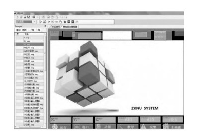
Figure 5 Operation interface
(1) Boot design
When starting up, wait for 2s, the DGUS system is turned on, then turn off the touch screen function, and initialize the variables of 0x0000~0x6000. After that, all the data displayed on the interface are the real data in the system, thus completing the initialization of the system.
(2) Touch design
The GUI PC software of DGUS can realize many functions, such as data variable input, addition and subtraction adjustment, data variable display, key return, etc. Icons include pop-up menu selection, drag adjustment, variable icon display, animation icon display, icon rotation indication, bit icon display, etc. Others include text display, dial clock display, real-time curve display, basic graphic display and so on.
(3) Design of data interaction
The design mainly changes all the displays by modifying variables. Setting different addresses for each different menu can avoid the repetition of a large amount of data and improve the data utilization efficiency.
Physical test
According to the design and manufacture of the prototype, many tests have proved that the system can control the manipulator freely, run stably and without shaking, and the setting of motor parameters is simple and convenient, the man-machine interface of the system is concise, and the operation is convenient and quick.
Conclusion
The manipulator has the advantages of flexible control, high stability, low cost and great practical popularization value. In future development, we can consider introducing network port design to realize networking control and monitoring, and introducing visual obstacle avoidance intelligent control technology.
Hardware design of injection molding machine control system
1. Overall design
The overall design of the control system is shown in Figure 1.
Fig. 1 overall design block diagram
1. Power supply module 2. Devin DGUS 3. Memory W25X16 4. U disk 5.RJ45 network port 6.I/O extended version 7. Injection molding machine 8. Servo system 9. Signal detection 10. Alarm.
2. Power supply module
Under normal circumstances, the servo motor needs a 24V power supply, the main control chip needs a 3.3V power supply, and the common optocoupler needs a 5V power supply. Therefore, the manipulator control board needs a power conversion circuit to reduce 24V to 5V and 5V to 3.3V The 24V to 5V circuit adopts the VRB2405YMD chip, which has an isolation function. It inputs a wide DC voltage of 18-75V, stably outputs 5V, and the maximum output current is 1.2A The circuit from 5V to 3.3V adopts linear voltage stabilizing chip AMS1117-3.3, and the input voltage is 4.7-12V.
From 24V to 5V, because the voltage input of the power supply module is limited, it will not work normally when the input voltage is lower than the lowest voltage of 18V, so the system needs to design a low-voltage detection module.
3. I/O port circuit
I/O input and output circuits mainly include:
(1) Optocoupler isolation circuit. All I/O ports are isolated by optocoupler to protect the main control board, and most of the isolation circuits in the design adopt EL817 optocoupler.
(2) Expand the I/O circuit. As the system needs more ports, under the condition that it can't meet the requirements, the design adopts an extended way, and 74HC164 and 74HC595 are selected.
(3) Relay controls the input and output circuit.
(4) Alarm output circuit, as shown in Figure 2.
Figure 2 Alarm circuit
(5) Pulse output interface circuit. The servo motor is controlled by pulse, which is first isolated and output by high-speed optocoupler A2631, and then
Then the pulse is output differentially through AM26LS31.
4. Communication port circuit, Flash memory circuit, network port and emergency stop circuit.
(1)RS-485 circuit
RS-485 communication is adopted, and the circuit is shown in Figure 3. Its anti-common mode interference ability is strong, the maximum transmission distance can reach 1200m, and the maximum number of interfaces can be mounted at 128.
(2) RS-232 circuit
To ensure the data is not lost, asynchronous communication is adopted, and the SP3232EEN chip is selected, which can provide bidirectional communication at the same time. The circuit schematic diagram is shown in Figure 4.
Figure 3 RS-485 communication interface
Figure 4 RS-232 Module
(3) USB communication circuit
In order to simplify the design, the USB chip CH376 with a file management system is adopted, which supports the SPI interface to operate the U disk. In the system, the U disk can be used to copy programs conveniently, and the chip needs five I/O ports.
(4) Flash circuit
Because the system needs to save the teaching program and editing program in time, the program will take up a lot of space, while the ROM in the STM32 chip is limited, so the ROM is expanded in the design, and the memory space of 2MB can be expanded by W25X16, which can meet the design requirements.
Software Design and Implementation of Injection Molding Machine Controller
The main program sequence is to power on, initialize all components of the STM32 system; Check whether there is any fault in the system, and troubleshoot it until there is no fault; Then start the system, enter the operating state, and choose manual or automatic operation; If the panic button is pressed, the system stops.
1. System initialization module
The system initialization module includes controller initialization, man-machine interface initialization and origin resetting module. The initialization of the man-machine interface mainly saves and restores the parameters to be saved, including the following parameters: system password, production management data, input polarity, the initial setting, system maintenance data, servo parameter setting, interface parameter setting and program saving. When starting up, the main control chip needs to read the data stored in the memory and then transmit it to the touch screen through the serial port. Click the home point at the upper left corner of the human-computer interaction screen, and send the data to the control board through the RS-232 serial port of the Diwan screen. The control board judges that the limit of the X/Y/Z axis, the alarm information of the I/O expansion board x1/x2/x3, the upper safety area of the front arm, and the position of the manipulator are all correct, and then sends the home point signal to get all axes home, marking the home point position at 1 and completing the home point.
2. Interrupt module
Firstly, configure the interrupt of STM32, set the interrupt priority of STM32 to the highest and turn on the interrupt. The system will detect whether there is an emergency stop, insufficient power supply voltage, servo alarm of X/Y/Z servo shaft, low air pressure, emergency stop of the injection molding machine, movement to the limit position, etc. in turn. If none of them happen, the buzzer and indicator light will not light up; Otherwise, it will turn on the light or sound the alarm according to the level, turn off the manipulator use signal, turn off the X/Y/Z axis pulse transmission, and send instructions to the screen every 0.4s to determine whether the communication between the control panel and the screen is interrupted.
3. Manipulator action program
The controller receives the manipulator action instruction sent by the screen and sends the corresponding action instruction to the manipulator after analysis and processing, including the X, Y and Z axes continuously rotating forward and backward and the fixed displacement relatively rotating forward and backward. Set the speed percentage and manual percentage through the menu to determine the final manual speed.
Design and Implementation of Man-machine Interface of Injection Molding Machine Controller System
DGUS is used to design a man-machine interface, and the overall operation interface of the system is shown in Figure 5.
Figure 5 Operation interface
(1) Boot design
When starting up, wait for 2s, the DGUS system is turned on, then turn off the touch screen function, and initialize the variables of 0x0000~0x6000. After that, all the data displayed on the interface are the real data in the system, thus completing the initialization of the system.
(2) Touch design
The GUI PC software of DGUS can realize many functions, such as data variable input, addition and subtraction adjustment, data variable display, key return, etc. Icons include pop-up menu selection, drag adjustment, variable icon display, animation icon display, icon rotation indication, bit icon display, etc. Others include text display, dial clock display, real-time curve display, basic graphic display and so on.
(3) Design of data interaction
The design mainly changes all the displays by modifying variables. Setting different addresses for each different menu can avoid the repetition of a large amount of data and improve the data utilization efficiency.
Physical test
According to the design and manufacture of the prototype, many tests have proved that the system can control the manipulator freely, run stably and without shaking, and the setting of motor parameters is simple and convenient, the man-machine interface of the system is concise, and the operation is convenient and quick.
Conclusion
The manipulator has the advantages of flexible control, high stability, low cost and great practical popularization value. In future development, we can consider introducing network port design to realize networking control and monitoring, and introducing visual obstacle avoidance intelligent control technology.
