
Design of PLC Six-axis Manipulators
With the rapid development of automation and intelligence in industrial production, the application of manipulators is increasingly extensive. It can replace manual work to complete some monotonous, repetitive and heavy tasks, or work in dangerous and harsh environments such as high temperature, loud noise and dust, such as workpiece sorting, material handling, welding, spraying and plastic products molding. The application of manipulators can not only save labor costs, reduce labor intensity, improve product quality and production efficiency, realize mechanization and automation of production, but also ensure personal safety and improve product safety. With PLC as the core, the hybrid drive mode of servo motor drive and hydraulic drive is adopted, the position information is fed back by the cable displacement sensor and encoder, and the system operation is carried out on the touch screen to realize the automatic handling of pipe fittings by the six-axis manipulator. The system integrates the advantages of electric drive and hydraulic drive and has the advantages of simple structure, strong anti-interference ability, low cost, fast system response and high control accuracy.
Composition and control requirements of the manipulator system
The manipulator is designed to be a six-axis manipulator for transporting pipe fittings. It is mainly composed of three parts: the actuator, the driving mechanism and the control system. The control system sends signals to the driving mechanism, and the driving mechanism sends instructions to the actuator to fulfill the control requirements. The actuating mechanism comprises a base, a big arm, a small arm and a handgrip; The control system takes PLC as the core and realizes the control of the manipulator's movement by writing and modifying programs. The driving mechanism adopts an electro-hydraulic hybrid driving mode, in which the base of the manipulator rotates, the boom lifts, the boom retracts and retracts, and the hand grabs and releases are hydraulically driven, while the wrist pitches and rotates electrically.
1. Mechanical structure of manipulator
The mechanical structure diagram of the manipulator is shown in Figure 2. The machine is composed of a base (with encoder) 1, support column 2, boom 3, boom 4, handgrip assembly 5, connecting assembly 6, boom cylinder 7 (with cable displacement sensor), boom cylinder 8 (with cable displacement sensor) and other components.
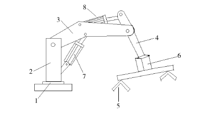
Figure 2 Schematic diagram of mechanical structure
2. Manipulator control requirements
The manipulator can complete the movements of the six-axis, such as base rotation, boom lifting, boom stretching, wrist rotation, wrist pitching, hand grasping and releasing. It can handle pipe fittings, with a grip range < 10 cm, the base rotation angle of 180, the wrist pitch angle of 90 and the wrist rotation angle of 180. There are two working modes, manual and automatic, to control the operation through the touch screen of the manipulator. When working in manual mode, you can click the corresponding button in the "Manual Mode" interface on the touch screen, so that the mechanical arm can jog to perform the action of a certain axis. Under the automatic working mode, the manipulator will automatically complete the whole set of actions according to the flow, and the flow is as follows: start → releasing the gripper → run to the pipe fitting position (ready to grab) → grab tightly → turn right at the base → extend the arm → rotate and pitch the wrist → turn left at the base → running to the pipe laying position (ready to lay) → loosen the gripper (ready to lay) → return to the original position → grab tightly.
Manipulator control system
1. System composition
In the manipulator control system, the electrical control system is very important, and the central control unit is the core of the electrical control system. Because PLC has the advantages of excellent performance, high-cost performance, strong anti-interference ability, simple programming, being suitable for a complex production environment, small system volume and low energy consumption, the manipulator control system adopts the PLC system, and Delta AS200 series PLC AS228P-A is selected. The manipulator control system is mainly composed of PLC, servo driver, servo motor, cable displacement sensor, steering gear, solenoid valve, encoder, etc.
2. Control principle
The manipulator system adopts hydraulic and electric hybrid driving modes. Among them, the four degrees of freedom of the manipulator, such as base rotation, boom lifting, boom stretching and hand grasping and releasing, are driven by hydraulic pressure, and the pitch and rotation of the wrist are driven by a servo motor.
(1) Hydraulic drive mode
Hydraulic drive adopts a new method of an electric control fluid, which uses low-power steering gear, connecting components and valves to make a new control valve, which is called a digital valve for the time being. It is connected to the valve through the steering gear connecting assembly, and the steering gear drives the valve core to adjust the opening of the valve, so as to adjust the flow of hydraulic oil. Taking the boom control as an example, a digital valve is installed on the inlet (return) oil pipe and the inlet (return) oil pipe of the boom oil cylinder, and the extension and retraction stroke of the piston rod of the boom oil cylinder is detected by the cable displacement sensor installed on the oil cylinder, so as to feedback the lifting and lowering the position of the manipulator boom. The cable displacement sensor transmits the detection signal to the PLC, and the PLC sends a pulse signal to the steering gear. The steering gear adjusts the opening of the valve and then controls the position and speed of the extension and retraction of the piston rod of the boom cylinder, thus realizing the control of the position and speed of the boom lifting and lowering. Similarly, by controlling the digital valve in the middle of the oil inlet and outlet pipe of the boom cylinder and the digital valve in the middle of the oil inlet and outlet pipe of the hydraulic motor, the extension and retraction of the boom and the control of the rotating position and speed of the base can be realized. This electric hydraulic control method solves the problems of traditional hydraulic servo control technology, such as complex system, poor anti-interference ability, high cost of hydraulic components, high requirement for cleanliness of hydraulic oil, the slow response speed of the system and low control accuracy.
(2) Electric driving mode
The electric drive adopts a servo drive, which consists of a servo motor and servo driver. Two servo motors are proposed, one is used to drive the wrist to rotate and the other is used to drive the wrist to pitch. The driver determines the output signal according to the control instruction and drives the servo motor through the PWM signal. There are many working modes of the servo, and the position control mode is selected by the system. Servo drive must match servo motor with servo driver. Ordinary motors can't be matched with servo drivers, only servo motors can be matched with servo drivers. Generally, there are two situations: one is to choose different brands of servo drivers and servo motors. When matching, check the rated voltage and current. The output voltage of the servo driver should be consistent with the rated voltage of the servo motor, and the rated current of the servo driver should not be less than the rated current of the servo motor. The other is to choose the servo motor and servo driver of the same brand. Usually, there is a selection list in the manual of the servo driver, which can be matched according to the requirements of the selection list. Panasonic servo motor MHMF042L1 and Panasonic servo driver MBDLT25SF011 are selected in this system.
(3) Programming
Every time the manipulator starts running, it needs to complete a reset action, in order to ensure that the manipulator is in the initial position before grabbing. The touch screen of the system sends instructions to PLC to control the action of the manipulator. Manipulator operation control is sequential control, and it is programmed by step-by-step sequence control instruction.
Conclusion
By using Delta PLC, Panasonic servo motor and servo driver, Delta touch screen, digital valve, etc. to build the control system of the manipulator, a six-axis manipulator handling device is designed by adopting the hybrid driving mode of servo motor driving and hydraulic driving, which realizes the automatic handling of pipe fittings. The system integrates the advantages of electric and hydraulic driving modes, gives full play to the advantages of large hydraulic output, reduces the volume and quality of mechanical gripper parts, and improves the space utilization rate. The manipulator is simple in structure, flexible in control and easy to operate, and has certain production and application value.
Composition and control requirements of the manipulator system
The manipulator is designed to be a six-axis manipulator for transporting pipe fittings. It is mainly composed of three parts: the actuator, the driving mechanism and the control system. The control system sends signals to the driving mechanism, and the driving mechanism sends instructions to the actuator to fulfill the control requirements. The actuating mechanism comprises a base, a big arm, a small arm and a handgrip; The control system takes PLC as the core and realizes the control of the manipulator's movement by writing and modifying programs. The driving mechanism adopts an electro-hydraulic hybrid driving mode, in which the base of the manipulator rotates, the boom lifts, the boom retracts and retracts, and the hand grabs and releases are hydraulically driven, while the wrist pitches and rotates electrically.
1. Mechanical structure of manipulator
The mechanical structure diagram of the manipulator is shown in Figure 2. The machine is composed of a base (with encoder) 1, support column 2, boom 3, boom 4, handgrip assembly 5, connecting assembly 6, boom cylinder 7 (with cable displacement sensor), boom cylinder 8 (with cable displacement sensor) and other components.
Figure 2 Schematic diagram of mechanical structure
2. Manipulator control requirements
The manipulator can complete the movements of the six-axis, such as base rotation, boom lifting, boom stretching, wrist rotation, wrist pitching, hand grasping and releasing. It can handle pipe fittings, with a grip range < 10 cm, the base rotation angle of 180, the wrist pitch angle of 90 and the wrist rotation angle of 180. There are two working modes, manual and automatic, to control the operation through the touch screen of the manipulator. When working in manual mode, you can click the corresponding button in the "Manual Mode" interface on the touch screen, so that the mechanical arm can jog to perform the action of a certain axis. Under the automatic working mode, the manipulator will automatically complete the whole set of actions according to the flow, and the flow is as follows: start → releasing the gripper → run to the pipe fitting position (ready to grab) → grab tightly → turn right at the base → extend the arm → rotate and pitch the wrist → turn left at the base → running to the pipe laying position (ready to lay) → loosen the gripper (ready to lay) → return to the original position → grab tightly.
Manipulator control system
1. System composition
In the manipulator control system, the electrical control system is very important, and the central control unit is the core of the electrical control system. Because PLC has the advantages of excellent performance, high-cost performance, strong anti-interference ability, simple programming, being suitable for a complex production environment, small system volume and low energy consumption, the manipulator control system adopts the PLC system, and Delta AS200 series PLC AS228P-A is selected. The manipulator control system is mainly composed of PLC, servo driver, servo motor, cable displacement sensor, steering gear, solenoid valve, encoder, etc.
2. Control principle
The manipulator system adopts hydraulic and electric hybrid driving modes. Among them, the four degrees of freedom of the manipulator, such as base rotation, boom lifting, boom stretching and hand grasping and releasing, are driven by hydraulic pressure, and the pitch and rotation of the wrist are driven by a servo motor.
(1) Hydraulic drive mode
Hydraulic drive adopts a new method of an electric control fluid, which uses low-power steering gear, connecting components and valves to make a new control valve, which is called a digital valve for the time being. It is connected to the valve through the steering gear connecting assembly, and the steering gear drives the valve core to adjust the opening of the valve, so as to adjust the flow of hydraulic oil. Taking the boom control as an example, a digital valve is installed on the inlet (return) oil pipe and the inlet (return) oil pipe of the boom oil cylinder, and the extension and retraction stroke of the piston rod of the boom oil cylinder is detected by the cable displacement sensor installed on the oil cylinder, so as to feedback the lifting and lowering the position of the manipulator boom. The cable displacement sensor transmits the detection signal to the PLC, and the PLC sends a pulse signal to the steering gear. The steering gear adjusts the opening of the valve and then controls the position and speed of the extension and retraction of the piston rod of the boom cylinder, thus realizing the control of the position and speed of the boom lifting and lowering. Similarly, by controlling the digital valve in the middle of the oil inlet and outlet pipe of the boom cylinder and the digital valve in the middle of the oil inlet and outlet pipe of the hydraulic motor, the extension and retraction of the boom and the control of the rotating position and speed of the base can be realized. This electric hydraulic control method solves the problems of traditional hydraulic servo control technology, such as complex system, poor anti-interference ability, high cost of hydraulic components, high requirement for cleanliness of hydraulic oil, the slow response speed of the system and low control accuracy.
(2) Electric driving mode
The electric drive adopts a servo drive, which consists of a servo motor and servo driver. Two servo motors are proposed, one is used to drive the wrist to rotate and the other is used to drive the wrist to pitch. The driver determines the output signal according to the control instruction and drives the servo motor through the PWM signal. There are many working modes of the servo, and the position control mode is selected by the system. Servo drive must match servo motor with servo driver. Ordinary motors can't be matched with servo drivers, only servo motors can be matched with servo drivers. Generally, there are two situations: one is to choose different brands of servo drivers and servo motors. When matching, check the rated voltage and current. The output voltage of the servo driver should be consistent with the rated voltage of the servo motor, and the rated current of the servo driver should not be less than the rated current of the servo motor. The other is to choose the servo motor and servo driver of the same brand. Usually, there is a selection list in the manual of the servo driver, which can be matched according to the requirements of the selection list. Panasonic servo motor MHMF042L1 and Panasonic servo driver MBDLT25SF011 are selected in this system.
(3) Programming
Every time the manipulator starts running, it needs to complete a reset action, in order to ensure that the manipulator is in the initial position before grabbing. The touch screen of the system sends instructions to PLC to control the action of the manipulator. Manipulator operation control is sequential control, and it is programmed by step-by-step sequence control instruction.
Conclusion
By using Delta PLC, Panasonic servo motor and servo driver, Delta touch screen, digital valve, etc. to build the control system of the manipulator, a six-axis manipulator handling device is designed by adopting the hybrid driving mode of servo motor driving and hydraulic driving, which realizes the automatic handling of pipe fittings. The system integrates the advantages of electric and hydraulic driving modes, gives full play to the advantages of large hydraulic output, reduces the volume and quality of mechanical gripper parts, and improves the space utilization rate. The manipulator is simple in structure, flexible in control and easy to operate, and has certain production and application value.
