
Parallel Automatic Material Taking Manipulators
The special manipulator of the injection molding machine is automatic production equipment that can imitate the function of the upper limb of the human body, and can automatically control it to transport products or operate tools according to the predetermined requirements. A robot is a machine specially equipped for the automation of injection molding production. It can play an extremely important role in reducing heavy manual labor, improving working conditions and safety in production, improving the productivity of injection molding machines, stabilizing product quality, reducing rejection rate, reducing production costs and enhancing the competitiveness of enterprises. At present, there are two types of injection molding machines: swing type and traverse type, which are mainly driven by pneumatic, stepping motor or servo motor. The movement of the machine is mainly linear, with few degrees of freedom, usually 2~3. With the continuous development of science and technology, robots in the future will develop towards high precision, multi-function, more intelligence and networking. It is believed that in the near future, the full-automatic production of injection molding workshop can be realized.
Drive system design
The manipulator of this project is a parallel manipulator, which is a typical three-degree-of-freedom structure. It is mainly suitable for medium and large horizontal injection molding machines and injection molds with double parting surfaces. The schematic diagram of the manipulator of the injection molding machine is shown in Figure 1.
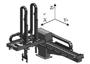
Figure 1 Three-dimensional schematic diagram of injection molding machine manipulator
In view of the fact that the workpiece and nozzle are taken out separately, two arms should be designed respectively, that is, the master hand and the deputy's hand. The master hand mainly uses a vacuum suction plate to suck the workpiece, which is mainly a sheet metal workpiece with a smooth surface, fragile material and heavy quality. The deputy uses pneumatic fingers to clamp the material inlet; Considering the large workpiece, the main wrist of the manipulator should have a certain rotation function in order to place the workpiece stably and not affect the appearance of the workpiece. X, Y and Z directions are guided by high-rigidity aluminum alloy extruded beams with high-rigidity precision linear slide rails and linear bearing, which meet the requirements of fast taking-out speed and long service life. The hand and the assistant are installed on the same Y-axis driving platform and move in the Y direction at the same time. The action sequence diagram of the manipulator is shown in Figure 2. The main technical indicators of this manipulator are as follows:
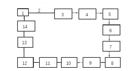
Figure 2 Action sequence diagram of the manipulator of injection molding machine
1. origin 2. wait for mold opening to eject the workpiece and nozzle. 3. the main and auxiliary arms are down along the z-axis. 4. the main and auxiliary arms are in front of the x-axis. 5. the main and auxiliary arms suck and clamp. 6. the main and auxiliary arms are behind the x-axis. 7. the main and auxiliary arms are up along the z-axis. 8. the wrist of the main arm rotates. 9. the main and auxiliary arms extend along the y axis. 10. the main arm is down along the z axis. 11. the main and auxiliary arms loosen the workpiece and water. 12. The main arm moves along the Z axis. 13. The wrist of the main hand rotates. 14. The main and auxiliary arms shrink along the Y axis.
(1) the maximum grabbing weight: 2kg; for the main hand;
(2) DOF of manipulator: 3;
(3) Coordinate form: three-dimensional coordinates;
(4) Arm motion parameters: the X-axis movable distance of the main hand is 200mm; The x-axis movable distance of the deputy is 100mm; The movable distance of the main z-axis of the hand is 600mm; The z-axis movable distance of the deputy is 670mm; The movable distance of y-axis is 1230mm; The rotation angle of the main wrist is 90;
(5) Positioning mode: X and Z axes are travel stops; the Y-axis direction is an electrical switch;
(6) Driving mode: X, Z axis and wrist rotation are driven by air pressure; Y-axis direction is driven by a motor;
(7) Positioning accuracy: ±0.3mm;
(8) Control mode: PLC control;
(9) Performance requirements: flexible grasping, stable delivery and reliable positioning. It can be known from the designed technical indexes that the driving system adopts two ways: pneumatic driving and motor driving. At present, the power systems mainly include pneumatic transmission, hydraulic transmission, motor drive and various internal combustion engine power drives.
And so on, but generally pneumatic drive, hydraulic drive and motor drive applications are the majority. Among them, the pneumatic transmission is quick and sensitive, and the working medium is air, which causes little environmental pollution. However, the gas itself is compressible, so the limitations of pneumatic transmission can not be ignored. For example, it is difficult to achieve high-precision positioning in a pneumatic servo system, and it is easy to shake at high speed. To sum up, pneumatic transmission is suitable for working in an environment of high speed, light load, high temperature and strong magnetic radiation, such as automatic production robots in factories. Hydraulic transmission is suitable for heavy industries with accurate positioning and high labor intensity, such as metallurgical machinery for the iron and steel industry, platform lifting machinery, excavators and other fields requiring strong power. The motor is mainly used in a high-precision, high-positioning, good working environment, mainly rotating and continuously moving occasions, such as the rotation of the spindle of the lathe and the translation of the crown block. Considering various factors, fully demonstrating its reliability, economy and rationality, the following choices are made.
Gripper: This mechanism is used to grasp the water intake. Since the grasping force is not too large, and it is far away from the support position, in order to reduce its weight and improve its accuracy, the pneumatic clamp is used here, and the Skyline clamp 1615D is selected, as shown in Figure 3.
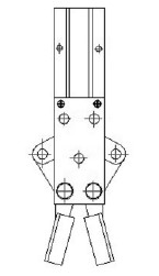
Fig. 3 pneumatic clamp
Main wrist rotation: The mechanism changes the workpiece in a vertical posture to release it in a horizontal posture. Because the resistance of wrist rotation is not big and the speed requirement is not big, the action is intermittent, and the price of a swing cylinder is much higher than that of the ordinary linear cylinder, so it is decided to use the cylinder to drive connecting rod to realize wrist rotation, and CM2D-25-65 cylinder is selected, as shown in Figure 4.
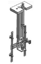
Fig. 4 Rotation mechanism of wrist of the main hand
The up-and-down movement of the main deputy's Z axis: in this direction, the movement distance of the arm is not large. In terms of power, the arm only needs to overcome the total gravity of the workpiece and the hand and the friction force of the up-and-down movement of the guide rail, so the required lifting force is not large. In addition, the arm is required to have a fast movement speed and work smoothly. Compared with the characteristics of pneumatic transmission, hydraulic transmission and motor drive, pneumatic transmission is selected in this direction, CG1F40-600 is selected for the main hand lifting cylinder and CG1F40-670 is selected for the deputy lifting cylinder. The partial schematic diagram of the main arm is shown in Figure 5.
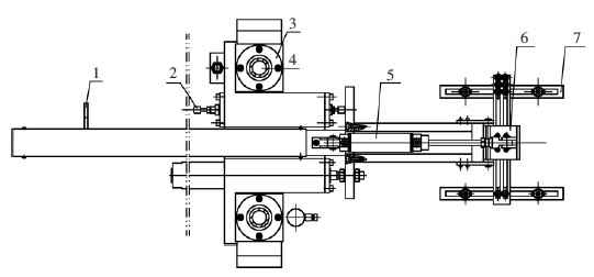
Fig. 5 Partial schematic diagram of the main arm
1. Metal limit block 2. Oil pressure vibration absorber 3. linear bearing 4. Linear axis 5. Cylinder 6. Connecting rod mechanism 7. Vacuum chuck mechanism.
X-direction movement of the main assistant: in this direction, the driving system only needs to take the workpiece and nozzle out of the mold, so the moving distance and driving force required for the movement are very small. Comparing the characteristics of various driving modes, it is most appropriate to choose pneumatic driving, and CG1F-25-200 is used as the main hand cylinder and CG1F-25-100 as the auxiliary cylinder.
Y-direction movement of the main deputy: in this direction, although the platform only needs to overcome the friction force of the guide rail mechanism, and the required driving force is very small, due to the large moving distance, the general cylinder is prone to instability when its stroke is too long, and the long-stroke cylinder is expensive and occupies a large space. Therefore, the motor drive mode is selected in this direction. Among them, two common types of motor drive are servo motor and stepping motor. The stepping motor is small in size and light in weight. By inputting a certain pulse to the stepping motor driver, the purpose of stepping motor control can be achieved. Therefore, stepping motor is often used in occasions with high control requirements and low rotating speed. Servo motor is developed on the basis of stepping motor, and its control precision and rotation speed are higher than those of stepping motor. However, because of its complex hardware configuration and control requirements and high price, the servo motor is often used in high-end technical fields with very high precision requirements. In the Y-axis movement direction, the distance accuracy of the platform movement is not high, so it is only necessary to realize the steady acceleration from low speed to a certain degree, then move at a constant speed, then decelerate to a certain value and then move at a constant speed to reach the predetermined position. Moreover, the platform movement speed is not high, reaching more than 500mm/s, so the stepping motor of 86BYG250-80 is selected.
Design of motion guide rail
The driving part provides the power needed for the mechanism to move linearly, while the guiding part ensures the mechanism moves in a certain direction and provides enough motion accuracy and support rigidity. A linear guide rail mechanism is used for the guide parts in the lifting direction and Y direction, and the layout of the guide parts is shown in Figure 6. Among them, the Y-direction guide part moves in the way of fixed guide rail and sliding block movement, and adopts double guide rails and double sliding blocks. The driving mechanism pushes the sliding block to move, and the sliding block drives the actuator to reciprocate linearly on the guide rail. EGW25CA is selected, and the guide rail length is 1720mm. The movement mode of the Z-direction lifting guide part is that the slide block is fixed and the guide rail moves. Single guide rail and double slide blocks are used to fix the slide block on the Z-direction fixed seat so that the guide rail moves up and down together with the actuator (arm grabbing mechanism), which mainly bears the lateral load. EGW20CA is selected, and the length of the guide rail is 1000mm. Linear bearing is selected as the guiding component in the horizontal direction of the manipulator. The movement mode of the X-direction guide part is that the linear axis is fixed, and the linear bearing and the loading slider reciprocate linearly, in which two linear axes are adopted, and two bearings are used on each linear axis. The model of the selected bearing is JBF35AWW, and the straight axis adopts a hollow axis.
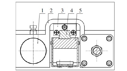
Fig. 6 Layout diagram of lifting direction guide parts
1. cylinder 2. manipulator fixing seat 3. linear slider 4. linear guide rail 5. guide rail fixing plate
Y-direction driving mode is driven by a stepping motor. As the output of the motor is rotary motion, a conversion mechanism is needed to convert the rotary motion output by the motor into linear motion with high precision. Considering comprehensively, the rolling ball screw with low cost and large lead is selected, and the elastic coupling is selected to connect the motor and the screw shaft and transmit torque, and the ball screw WTF2060-3 is selected. The partial schematic diagram of the XY platform is shown in Figure 7.
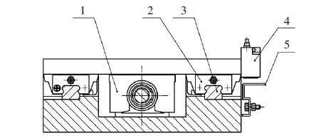
Fig. 7 partial schematic diagram of XY platform
1. Ball screw mechanism 2. Linear slider 3. Linear guide 4. Inductive proximity switch 5. Metal inductive proximity switch.
Design of buffer mechanism
The movement characteristics of the manipulator are analyzed, and the buffer mechanism of the oil pressure vibration absorber is adopted in the X and Z directions with adjustable displacement. The buffer mechanism works in the damping and buffering mode of the oil pressure circuit, with stable buffer and good effect. In addition, the damping and buffering mechanism of the oil pressure circuit are matched with the metal limit block and can be used as a mechanical limit part, so the buffering mechanism integrates buffering and positioning functions, greatly simplifies the mechanical system, and thus solves the problems of shaking and positioning caused by pneumatic transmission in X and Z directions. Choose the buffer of the RB1411 model. The buffer mechanism in the Y direction is optimized by the running speed of the motor, which reduces the impact and vibration of the mechanism. By changing the speed of the motor, the motor moves at a lower speed at the beginning and end of the operation but moves at a high speed in the middle, which can not only ensure the speed and efficiency of the mechanism but also effectively reduce the impact and buffer of the mechanism. The limiting mechanism is composed of an inductive proximity switch and a metal induction piece, and the S25 inductive proximity switch is selected.
Conclusion
The main hand of the parallel automatic material-taking manipulator of the injection molding machine uses a vacuum to suck the workpiece, and the auxiliary hand uses a pneumatic clamp to clamp the water intake. The driving system of the manipulator is composed of cylinder drive and motor drive. Because of the long distance in the Y-axis direction, the stepping motor drive mode is skillfully adopted, which makes the manipulator move smoothly and position accurately. In other moving directions, the cylinder is used for driving, and the mechanical positioning method greatly simplifies the structure of the equipment, and reduces the requirements of the manipulator on the control system. In terms of guide parts and buffer, linear guide rail and linear bearing are selected for guide parts, ball screw mechanism is selected for reversing gear, and oil pressure vibration absorber and motor are optimized for buffer mechanism, which meets the requirements of high working requirement, high reliability and continuous working of the manipulator.
Drive system design
The manipulator of this project is a parallel manipulator, which is a typical three-degree-of-freedom structure. It is mainly suitable for medium and large horizontal injection molding machines and injection molds with double parting surfaces. The schematic diagram of the manipulator of the injection molding machine is shown in Figure 1.
Figure 1 Three-dimensional schematic diagram of injection molding machine manipulator
In view of the fact that the workpiece and nozzle are taken out separately, two arms should be designed respectively, that is, the master hand and the deputy's hand. The master hand mainly uses a vacuum suction plate to suck the workpiece, which is mainly a sheet metal workpiece with a smooth surface, fragile material and heavy quality. The deputy uses pneumatic fingers to clamp the material inlet; Considering the large workpiece, the main wrist of the manipulator should have a certain rotation function in order to place the workpiece stably and not affect the appearance of the workpiece. X, Y and Z directions are guided by high-rigidity aluminum alloy extruded beams with high-rigidity precision linear slide rails and linear bearing, which meet the requirements of fast taking-out speed and long service life. The hand and the assistant are installed on the same Y-axis driving platform and move in the Y direction at the same time. The action sequence diagram of the manipulator is shown in Figure 2. The main technical indicators of this manipulator are as follows:
Figure 2 Action sequence diagram of the manipulator of injection molding machine
1. origin 2. wait for mold opening to eject the workpiece and nozzle. 3. the main and auxiliary arms are down along the z-axis. 4. the main and auxiliary arms are in front of the x-axis. 5. the main and auxiliary arms suck and clamp. 6. the main and auxiliary arms are behind the x-axis. 7. the main and auxiliary arms are up along the z-axis. 8. the wrist of the main arm rotates. 9. the main and auxiliary arms extend along the y axis. 10. the main arm is down along the z axis. 11. the main and auxiliary arms loosen the workpiece and water. 12. The main arm moves along the Z axis. 13. The wrist of the main hand rotates. 14. The main and auxiliary arms shrink along the Y axis.
(1) the maximum grabbing weight: 2kg; for the main hand;
(2) DOF of manipulator: 3;
(3) Coordinate form: three-dimensional coordinates;
(4) Arm motion parameters: the X-axis movable distance of the main hand is 200mm; The x-axis movable distance of the deputy is 100mm; The movable distance of the main z-axis of the hand is 600mm; The z-axis movable distance of the deputy is 670mm; The movable distance of y-axis is 1230mm; The rotation angle of the main wrist is 90;
(5) Positioning mode: X and Z axes are travel stops; the Y-axis direction is an electrical switch;
(6) Driving mode: X, Z axis and wrist rotation are driven by air pressure; Y-axis direction is driven by a motor;
(7) Positioning accuracy: ±0.3mm;
(8) Control mode: PLC control;
(9) Performance requirements: flexible grasping, stable delivery and reliable positioning. It can be known from the designed technical indexes that the driving system adopts two ways: pneumatic driving and motor driving. At present, the power systems mainly include pneumatic transmission, hydraulic transmission, motor drive and various internal combustion engine power drives.
And so on, but generally pneumatic drive, hydraulic drive and motor drive applications are the majority. Among them, the pneumatic transmission is quick and sensitive, and the working medium is air, which causes little environmental pollution. However, the gas itself is compressible, so the limitations of pneumatic transmission can not be ignored. For example, it is difficult to achieve high-precision positioning in a pneumatic servo system, and it is easy to shake at high speed. To sum up, pneumatic transmission is suitable for working in an environment of high speed, light load, high temperature and strong magnetic radiation, such as automatic production robots in factories. Hydraulic transmission is suitable for heavy industries with accurate positioning and high labor intensity, such as metallurgical machinery for the iron and steel industry, platform lifting machinery, excavators and other fields requiring strong power. The motor is mainly used in a high-precision, high-positioning, good working environment, mainly rotating and continuously moving occasions, such as the rotation of the spindle of the lathe and the translation of the crown block. Considering various factors, fully demonstrating its reliability, economy and rationality, the following choices are made.
Gripper: This mechanism is used to grasp the water intake. Since the grasping force is not too large, and it is far away from the support position, in order to reduce its weight and improve its accuracy, the pneumatic clamp is used here, and the Skyline clamp 1615D is selected, as shown in Figure 3.
Fig. 3 pneumatic clamp
Main wrist rotation: The mechanism changes the workpiece in a vertical posture to release it in a horizontal posture. Because the resistance of wrist rotation is not big and the speed requirement is not big, the action is intermittent, and the price of a swing cylinder is much higher than that of the ordinary linear cylinder, so it is decided to use the cylinder to drive connecting rod to realize wrist rotation, and CM2D-25-65 cylinder is selected, as shown in Figure 4.
Fig. 4 Rotation mechanism of wrist of the main hand
The up-and-down movement of the main deputy's Z axis: in this direction, the movement distance of the arm is not large. In terms of power, the arm only needs to overcome the total gravity of the workpiece and the hand and the friction force of the up-and-down movement of the guide rail, so the required lifting force is not large. In addition, the arm is required to have a fast movement speed and work smoothly. Compared with the characteristics of pneumatic transmission, hydraulic transmission and motor drive, pneumatic transmission is selected in this direction, CG1F40-600 is selected for the main hand lifting cylinder and CG1F40-670 is selected for the deputy lifting cylinder. The partial schematic diagram of the main arm is shown in Figure 5.
Fig. 5 Partial schematic diagram of the main arm
1. Metal limit block 2. Oil pressure vibration absorber 3. linear bearing 4. Linear axis 5. Cylinder 6. Connecting rod mechanism 7. Vacuum chuck mechanism.
X-direction movement of the main assistant: in this direction, the driving system only needs to take the workpiece and nozzle out of the mold, so the moving distance and driving force required for the movement are very small. Comparing the characteristics of various driving modes, it is most appropriate to choose pneumatic driving, and CG1F-25-200 is used as the main hand cylinder and CG1F-25-100 as the auxiliary cylinder.
Y-direction movement of the main deputy: in this direction, although the platform only needs to overcome the friction force of the guide rail mechanism, and the required driving force is very small, due to the large moving distance, the general cylinder is prone to instability when its stroke is too long, and the long-stroke cylinder is expensive and occupies a large space. Therefore, the motor drive mode is selected in this direction. Among them, two common types of motor drive are servo motor and stepping motor. The stepping motor is small in size and light in weight. By inputting a certain pulse to the stepping motor driver, the purpose of stepping motor control can be achieved. Therefore, stepping motor is often used in occasions with high control requirements and low rotating speed. Servo motor is developed on the basis of stepping motor, and its control precision and rotation speed are higher than those of stepping motor. However, because of its complex hardware configuration and control requirements and high price, the servo motor is often used in high-end technical fields with very high precision requirements. In the Y-axis movement direction, the distance accuracy of the platform movement is not high, so it is only necessary to realize the steady acceleration from low speed to a certain degree, then move at a constant speed, then decelerate to a certain value and then move at a constant speed to reach the predetermined position. Moreover, the platform movement speed is not high, reaching more than 500mm/s, so the stepping motor of 86BYG250-80 is selected.
Design of motion guide rail
The driving part provides the power needed for the mechanism to move linearly, while the guiding part ensures the mechanism moves in a certain direction and provides enough motion accuracy and support rigidity. A linear guide rail mechanism is used for the guide parts in the lifting direction and Y direction, and the layout of the guide parts is shown in Figure 6. Among them, the Y-direction guide part moves in the way of fixed guide rail and sliding block movement, and adopts double guide rails and double sliding blocks. The driving mechanism pushes the sliding block to move, and the sliding block drives the actuator to reciprocate linearly on the guide rail. EGW25CA is selected, and the guide rail length is 1720mm. The movement mode of the Z-direction lifting guide part is that the slide block is fixed and the guide rail moves. Single guide rail and double slide blocks are used to fix the slide block on the Z-direction fixed seat so that the guide rail moves up and down together with the actuator (arm grabbing mechanism), which mainly bears the lateral load. EGW20CA is selected, and the length of the guide rail is 1000mm. Linear bearing is selected as the guiding component in the horizontal direction of the manipulator. The movement mode of the X-direction guide part is that the linear axis is fixed, and the linear bearing and the loading slider reciprocate linearly, in which two linear axes are adopted, and two bearings are used on each linear axis. The model of the selected bearing is JBF35AWW, and the straight axis adopts a hollow axis.
Fig. 6 Layout diagram of lifting direction guide parts
1. cylinder 2. manipulator fixing seat 3. linear slider 4. linear guide rail 5. guide rail fixing plate
Y-direction driving mode is driven by a stepping motor. As the output of the motor is rotary motion, a conversion mechanism is needed to convert the rotary motion output by the motor into linear motion with high precision. Considering comprehensively, the rolling ball screw with low cost and large lead is selected, and the elastic coupling is selected to connect the motor and the screw shaft and transmit torque, and the ball screw WTF2060-3 is selected. The partial schematic diagram of the XY platform is shown in Figure 7.
Fig. 7 partial schematic diagram of XY platform
1. Ball screw mechanism 2. Linear slider 3. Linear guide 4. Inductive proximity switch 5. Metal inductive proximity switch.
Design of buffer mechanism
The movement characteristics of the manipulator are analyzed, and the buffer mechanism of the oil pressure vibration absorber is adopted in the X and Z directions with adjustable displacement. The buffer mechanism works in the damping and buffering mode of the oil pressure circuit, with stable buffer and good effect. In addition, the damping and buffering mechanism of the oil pressure circuit are matched with the metal limit block and can be used as a mechanical limit part, so the buffering mechanism integrates buffering and positioning functions, greatly simplifies the mechanical system, and thus solves the problems of shaking and positioning caused by pneumatic transmission in X and Z directions. Choose the buffer of the RB1411 model. The buffer mechanism in the Y direction is optimized by the running speed of the motor, which reduces the impact and vibration of the mechanism. By changing the speed of the motor, the motor moves at a lower speed at the beginning and end of the operation but moves at a high speed in the middle, which can not only ensure the speed and efficiency of the mechanism but also effectively reduce the impact and buffer of the mechanism. The limiting mechanism is composed of an inductive proximity switch and a metal induction piece, and the S25 inductive proximity switch is selected.
Conclusion
The main hand of the parallel automatic material-taking manipulator of the injection molding machine uses a vacuum to suck the workpiece, and the auxiliary hand uses a pneumatic clamp to clamp the water intake. The driving system of the manipulator is composed of cylinder drive and motor drive. Because of the long distance in the Y-axis direction, the stepping motor drive mode is skillfully adopted, which makes the manipulator move smoothly and position accurately. In other moving directions, the cylinder is used for driving, and the mechanical positioning method greatly simplifies the structure of the equipment, and reduces the requirements of the manipulator on the control system. In terms of guide parts and buffer, linear guide rail and linear bearing are selected for guide parts, ball screw mechanism is selected for reversing gear, and oil pressure vibration absorber and motor are optimized for buffer mechanism, which meets the requirements of high working requirement, high reliability and continuous working of the manipulator.
