Parametric Design and Vibration Analysis of an Injection Robot Arm(Part One)
Abstract: With the development of the plastic industry, the combination of the injection molding robot arm and injection molding machine has become an inevitable development of the industry. The combination of the two greatly improves the production efficiency of the factory. The production efficiency of the injection molding machine depends on the working efficiency of the injection robot arm to a large extent. Use VBA to obtain the secondary development of SolidWorks based on parametric design in order to improve the design efficiency of the injection robot arm. The key parts of the robot arm were parametrically designed, which shortened the design cycle of the robot arm. Then use Ansys software to analyze the harmonic response of the key parts of the robot arm. According to the analysis results, the main arm beam of the robot arm is optimized to reduce the vibration during the work of the robot arm.
1. Introduction
In terms of model modeling of parametric design, there are two main types of secondary development of traditional SolidWorks. One is to use a series of part design tables and the other is to customize a size driven form. Both methods have their disadvantages. Using VBA as the development tool, a secondary development method based on SolidWorks dimension-driven modeling is proposed, which improves the traditional dimension-driven modeling. Any model with dimensions marked in the design can be changed easily and quickly by using this method. The method is applied to the parametric design of the injection robot arm, which greatly improves the design efficiency of the robot arm. The vibration problem of the robot arm is also a design factor to be considered. Use Ansys software to analyze the harmonic response and optimize design of the designed robot arm, which reduces the vibration of the robot arm during the production process and improves the overall dynamic characteristics of the robot arm.
2. The development process of the parametric design system of the injection robot arm
2.1 Development ideas
Use SolidWorks to create a model of the robot arm, and SolidWorks will generate a size name for each part of the robot arm. The features of parts are divided into two-dimensional features and three-dimensional features. The form of the 3D feature is generally D1@ stretch and the name of the 2D sketch is generally in the form of D1@ sketch 2. The amount of dimensions in the sketch is determined by the designer when drawing the sketch. By going through features of parts and reading the amount of dimensions contained in each feature, the name of the dimension data can be restored in the program, and then assign values to each dimension to reconstruct the model.
2.2 Three-dimensional modeling of an injection robot arm
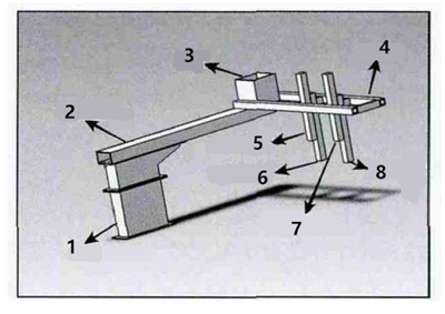
In order to realize the parametric design of the injection robot arm and facilitate the dynamic analysis of the robot arm, it is necessary to simplify the robot arm with complex structure when modeling. Simplify some minor parts of robot arms which have little effect on the dynamic analysis of the robot arm. The model of the robot arm is simplified based on the above principles. The main components include bases, the first arm beams, cases, the second arm beams, the first arms of forearms, the second arms of forearms, main arms of rear arms and the second arms of the rear arms. The simplified robot arm model is shown in the Figure 1.
Fig.1 The simplified robot arm model
1. Introduction
In terms of model modeling of parametric design, there are two main types of secondary development of traditional SolidWorks. One is to use a series of part design tables and the other is to customize a size driven form. Both methods have their disadvantages. Using VBA as the development tool, a secondary development method based on SolidWorks dimension-driven modeling is proposed, which improves the traditional dimension-driven modeling. Any model with dimensions marked in the design can be changed easily and quickly by using this method. The method is applied to the parametric design of the injection robot arm, which greatly improves the design efficiency of the robot arm. The vibration problem of the robot arm is also a design factor to be considered. Use Ansys software to analyze the harmonic response and optimize design of the designed robot arm, which reduces the vibration of the robot arm during the production process and improves the overall dynamic characteristics of the robot arm.
2. The development process of the parametric design system of the injection robot arm
2.1 Development ideas
Use SolidWorks to create a model of the robot arm, and SolidWorks will generate a size name for each part of the robot arm. The features of parts are divided into two-dimensional features and three-dimensional features. The form of the 3D feature is generally D1@ stretch and the name of the 2D sketch is generally in the form of D1@ sketch 2. The amount of dimensions in the sketch is determined by the designer when drawing the sketch. By going through features of parts and reading the amount of dimensions contained in each feature, the name of the dimension data can be restored in the program, and then assign values to each dimension to reconstruct the model.
2.2 Three-dimensional modeling of an injection robot arm
In order to realize the parametric design of the injection robot arm and facilitate the dynamic analysis of the robot arm, it is necessary to simplify the robot arm with complex structure when modeling. Simplify some minor parts of robot arms which have little effect on the dynamic analysis of the robot arm. The model of the robot arm is simplified based on the above principles. The main components include bases, the first arm beams, cases, the second arm beams, the first arms of forearms, the second arms of forearms, main arms of rear arms and the second arms of the rear arms. The simplified robot arm model is shown in the Figure 1.
Fig.1 The simplified robot arm model
1. Bases 2. Main arm beams 3. Cases 4. The second arm beams 5. Main arms of rear arms 6. The second arms of rear arms 7. Main arms of forearms 8. The second arms of forearms
2.3 Parametric design of the main components of the injection robot arm
First, open SolidWorks, and the program will get the name of the part. The program starts to go through the feature tree of the part. The feature tree contains some content that does not have size features, such as remarks, comments, light source, materials, zero point, etc. The content is not within the scope of API traversal, because sequences of feature trees in which the API traverses is from top to bottom, and the features of the part are all under the origin feature. During the traversal of the features, the program will determine whether the current feature is the origin. If it is the origin, the traversal of features and the amount of dimensions of the part will begin next time. The principle of the program determining the amount of dimensions is like this. The program judges repeatedly and will get a return value each time. When the return value is smaller than the size contained in the sketch, the program continues to loop until the return value is greater than the size contained in the sketch. The program ends the loop, and the amount of dimensions contained in the sketch is obtained. The program will input the amount of dimensions into arrays, and dynamically load size-driven forms based on every feature of the part and the amount of dimensions. Then an input box of every name of the part and its corresponding size will be showed on the form. The user enters the corresponding size and clicks OK, and the program can automatically complete the size-driven modeling by calling the SolidWorks API function.
