Design and Analysis of an Injection Robotic Arm (Part Two)
Design of picking components
The hands of the injection robotic arm can be specially designed according to the characteristics of the specific injection product to pick and place the product and recycle waste. Therefore, the hand structure is determined by factors such as the size, shape and weight of the product. The hand structure of the injection robotic arm is generally divided into adsorption type and clamping type. In order to ensure the reliability of the clamping structure, the clamping force is generally designed to be great. Although the stability of the clamping is ensured, it is easy to cause damage to the product. Therefore, the clamping type is generally used for picking and placing waste. The adsorption type generally does not cause damage to the product, and the shape of the object that can be grasped is less restricted, which is widely used for picking and placing injection products. On the first arm of the robotic arm designed in the article, an adsorption type gripper is installed to pick and place products, and clamping of waste is realized by a clamping gripper installed on the second arm.
The clamping part at the end of the first arm is shown in the Figure 4. It can be seen from the Figure 4 that the end of the first arm is mainly composed of a cylinder, a bracket, a flip claw and a sensor. The entire part is fixed and connected to the movable arm of the first arm through the bracket. The cylinder and the bracket are connected by a shaft, and the flip claw is mounted on the push rod of the cylinder. The flip claw is connected to the bracket through a shaft, and the flipping of the flipping claw is realized by controlling the push-and-pull movement of the cylinder push rod. Two position sensors are installed on the cylinder wall to have feedback of the state of the flipping claw.
Figure 4 Clamping structure at the end of the first arm
1. Cylinders 2. Sensors 3. Brackets 4. Flip claws
Figure 5 shows the clamping mechanism of the second arm. The second arm is mainly composed of connectors, finger cylinders and clamps. The finger cylinder is connected to the movable arm of the second arm through a connector. The finger cylinder is equipped with clamps. When the cylinder push rod moves, the clamps can be controlled to obtain clamping and releasing actions.
Figure 5 Clamping structure at the end of the second arm

Figure 5 Clamping structure at the end of the second arm
1. Clamps 2. Connectors 3. Finger cylinders
Kinematics simulation analysis of the injection robotic arm
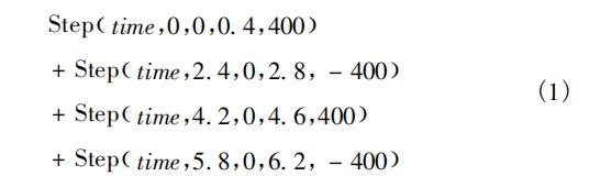
Simplify the three-dimensional model established by Solidworks and remove some components such as bearings, cases and sensors which basically have no effect on the results, and input them into ADAMS for simulation analysis. First, set the basic properties of the model, selecting and setting the material and density of each component, and then add kinematic pairs and constraints. After the above settings are completed, add a drive. Set the simulation time to 8 seconds, and the simulation steps to 1,000. Set the driving function of upward and downward movement of the first and second arm as the equation (1).
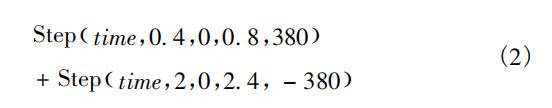
The driving function of the pull-out motion of the first arm is shown in the equation (2).
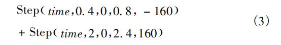
The driving function of the pull-out motion of the second arm is shown in the equation (3).
The driving function of the horizontal motion is shown in the equation (4).
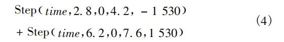
Fig. 6 shows the displacement and speed curves of the first and second arm moving up and down. It can be seen from the Figure 6 that the line one represents the displacement curve of the first and second arm moving up and down and the line two represents the speed curve of the first and second arm moving up and down. When the robotic arm is moving up and down on the first and second arm, there are four displacement, among which the maximum displacement is 800mm and the maximum speed is 3000mm/s.
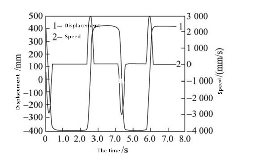
Figure 6 Displacement and speed curves of the robotic arm when the first and second arms move up and down at the first and second arms.
The displacement and speed curves of the pulling motion of the first and second arm are shown in the Figures 7 and 8. It can be seen from the Figures 7 and 8, the line one represents the displacement curve, and the line two represents the speed curve. When the robotic arm is in the pulling motion, there are two displacement processes. The maximum displacement of the first arm is 380mm and the maximum speed is 1400mm/s. The maximum displacement of the second arm is 160mm, and the maximum speed is 600mm/s.
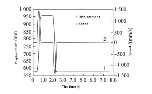
Figure 7 Displacement and speed curves of the robotic arm when the first arm is in the pulling motion.
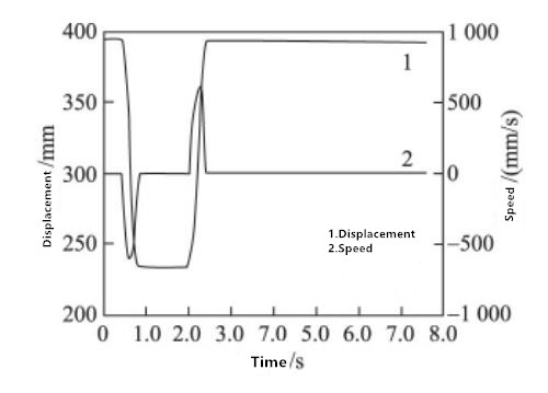
Figure 8 Displacement and speed curve of the robotic arm when the second arm is in the pulling motion.
Figure 9 shows the displacement and speed curves of the robotic arm when it moves horizontally. It can be seen from the Figure 9 that the line one represents the displacement curve of horizontal motion, and the line two represents the speed curve of horizontal motion. When the robotic arm is in the horizontal motion, there are two displacement processes. The maximum displacement is 1530mm, and the maximum speed is 1600mm/s.
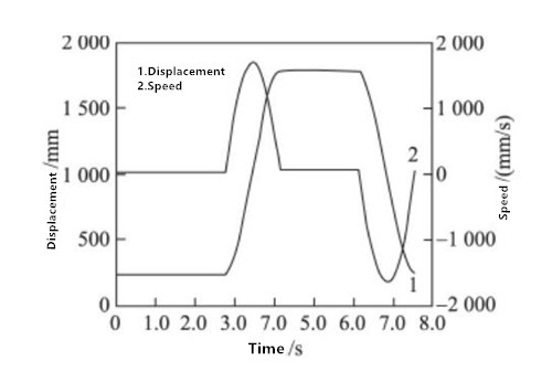
Figure 9 Displacement and speed curves of the robotic arm in the horizontal motion
It can be seen from Figures 6, 7, 8 and 9 that the displacement and speed of the three directions of upward and downward movement, pulling and horizontal movement are all changed synchronously, which is consistent with the law of movement, and the speed curves are smooth and without sharp corners. It shows that when the robotic arm is in various movements, it is relatively stable and there is no obvious vibration, which meet the working requirements for the injection robotic arm.
Conclusion
According to the characteristics of the loading and unloading of the horizontal injection molding machine, a robotic arm with five-axis servo is designed for the injection molding machine, which is mainly used for the picking process of the workpiece or waste. It is mainly composed of the base, the beam mechanism, the cantilever mechanism, the first and second arm mechanism and the hand mechanism. After simplifying the drawn three-dimensional model of the injection robotic arm, input it into ADAMS to analyze the kinematics of the injection robotic arm, and obtain the curves of the displacement and speed in the horizontal movement of the robotic arm, the up and down movement of the first and second arm and the pulling movement of the first and second arm along the cantilever 3 movements. The curves are smoothly without sharp corners, which proves that the robotic arm can work smoothly, verifies the rationality of the design and provides theoretical support for the motion control of the injection robotic arm.
Simplify the three-dimensional model established by Solidworks and remove some components such as bearings, cases and sensors which basically have no effect on the results, and input them into ADAMS for simulation analysis. First, set the basic properties of the model, selecting and setting the material and density of each component, and then add kinematic pairs and constraints. After the above settings are completed, add a drive. Set the simulation time to 8 seconds, and the simulation steps to 1,000. Set the driving function of upward and downward movement of the first and second arm as the equation (1).
The driving function of the pull-out motion of the first arm is shown in the equation (2).
The driving function of the pull-out motion of the second arm is shown in the equation (3).
The driving function of the horizontal motion is shown in the equation (4).
Fig. 6 shows the displacement and speed curves of the first and second arm moving up and down. It can be seen from the Figure 6 that the line one represents the displacement curve of the first and second arm moving up and down and the line two represents the speed curve of the first and second arm moving up and down. When the robotic arm is moving up and down on the first and second arm, there are four displacement, among which the maximum displacement is 800mm and the maximum speed is 3000mm/s.
Figure 6 Displacement and speed curves of the robotic arm when the first and second arms move up and down at the first and second arms.
The displacement and speed curves of the pulling motion of the first and second arm are shown in the Figures 7 and 8. It can be seen from the Figures 7 and 8, the line one represents the displacement curve, and the line two represents the speed curve. When the robotic arm is in the pulling motion, there are two displacement processes. The maximum displacement of the first arm is 380mm and the maximum speed is 1400mm/s. The maximum displacement of the second arm is 160mm, and the maximum speed is 600mm/s.
Figure 7 Displacement and speed curves of the robotic arm when the first arm is in the pulling motion.
Figure 8 Displacement and speed curve of the robotic arm when the second arm is in the pulling motion.
Figure 9 shows the displacement and speed curves of the robotic arm when it moves horizontally. It can be seen from the Figure 9 that the line one represents the displacement curve of horizontal motion, and the line two represents the speed curve of horizontal motion. When the robotic arm is in the horizontal motion, there are two displacement processes. The maximum displacement is 1530mm, and the maximum speed is 1600mm/s.
Figure 9 Displacement and speed curves of the robotic arm in the horizontal motion
It can be seen from Figures 6, 7, 8 and 9 that the displacement and speed of the three directions of upward and downward movement, pulling and horizontal movement are all changed synchronously, which is consistent with the law of movement, and the speed curves are smooth and without sharp corners. It shows that when the robotic arm is in various movements, it is relatively stable and there is no obvious vibration, which meet the working requirements for the injection robotic arm.
Conclusion
According to the characteristics of the loading and unloading of the horizontal injection molding machine, a robotic arm with five-axis servo is designed for the injection molding machine, which is mainly used for the picking process of the workpiece or waste. It is mainly composed of the base, the beam mechanism, the cantilever mechanism, the first and second arm mechanism and the hand mechanism. After simplifying the drawn three-dimensional model of the injection robotic arm, input it into ADAMS to analyze the kinematics of the injection robotic arm, and obtain the curves of the displacement and speed in the horizontal movement of the robotic arm, the up and down movement of the first and second arm and the pulling movement of the first and second arm along the cantilever 3 movements. The curves are smoothly without sharp corners, which proves that the robotic arm can work smoothly, verifies the rationality of the design and provides theoretical support for the motion control of the injection robotic arm.
