Design and Analysis of an Injection Robotic Arm (Part One)
Abstract
With the rapid development of the injection molding industry at home and abroad, the traditional manual material loading and unloading can no longer meet the needs of industrialization, and the injection robotic arm has solved this problem. A special injection robotic arm is designed according to the characteristics of the material loading and unloading of the horizontal injection molding machine, which is mainly composed of the base, beam mechanism, first and second arm, hand mechanism and other components and realizes the movement in 3 directions. The drawn three-dimensional model of the injection robotic arm was simplified and input into ADAMS, and the kinematics simulation analysis was performed on it. The displacement and speed curves of each movement of the robotic arm were obtained. The displacement and speed in the three directions all changed synchronously and all the speed curves are smooth and without sharp corners. Therefore, the robotic arm is relatively stable during various movements and there is no obvious vibration, which meets the working requirements for the injection robotic arm, verifies the rationality of the design, and provides theoretical support for the motion control of the injection robotic arm.
Overall structure of an injection robotic arm
According to the structural characteristics of the horizontal injection molding machine and the loading and unloading conditions, the injection molding robotic arm designed in this article is a five-axis servo robotic arm which is mainly used for the picking process of workpieces or scraps. The structure is shown in Figure 1. It can be seen from Figure 1 that it is mainly composed of a base, a beam mechanism, a cantilever mechanism, a first and second mechanism and a hand mechanism, which can obtain movement in 3 directions, namely the horizontal movement along the beam, the up and down movement of the first and second arm and the pull-out movement of the first and second arm along the cantilever and the movements are driven by a servo motor. The horizontal movement is driven by the servo motor and slides linearly along the guide rail. The up and down movement of the first and second arm are driven by the servo motor. The pull-out movement of the first and second arm is driven by the servo motor to drive the sliding seat on the first and second arm to move horizontally along the cantilever, and the movement of the hand mechanism can be realized pneumatically.
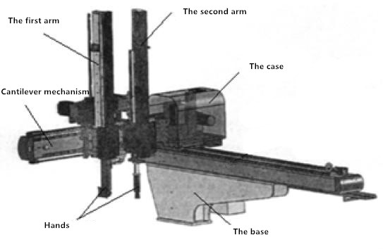
Figure 1 Basic structure of the injection robotic arm
Structure design of main components
With the rapid development of the injection molding industry at home and abroad, the traditional manual material loading and unloading can no longer meet the needs of industrialization, and the injection robotic arm has solved this problem. A special injection robotic arm is designed according to the characteristics of the material loading and unloading of the horizontal injection molding machine, which is mainly composed of the base, beam mechanism, first and second arm, hand mechanism and other components and realizes the movement in 3 directions. The drawn three-dimensional model of the injection robotic arm was simplified and input into ADAMS, and the kinematics simulation analysis was performed on it. The displacement and speed curves of each movement of the robotic arm were obtained. The displacement and speed in the three directions all changed synchronously and all the speed curves are smooth and without sharp corners. Therefore, the robotic arm is relatively stable during various movements and there is no obvious vibration, which meets the working requirements for the injection robotic arm, verifies the rationality of the design, and provides theoretical support for the motion control of the injection robotic arm.
Overall structure of an injection robotic arm
According to the structural characteristics of the horizontal injection molding machine and the loading and unloading conditions, the injection molding robotic arm designed in this article is a five-axis servo robotic arm which is mainly used for the picking process of workpieces or scraps. The structure is shown in Figure 1. It can be seen from Figure 1 that it is mainly composed of a base, a beam mechanism, a cantilever mechanism, a first and second mechanism and a hand mechanism, which can obtain movement in 3 directions, namely the horizontal movement along the beam, the up and down movement of the first and second arm and the pull-out movement of the first and second arm along the cantilever and the movements are driven by a servo motor. The horizontal movement is driven by the servo motor and slides linearly along the guide rail. The up and down movement of the first and second arm are driven by the servo motor. The pull-out movement of the first and second arm is driven by the servo motor to drive the sliding seat on the first and second arm to move horizontally along the cantilever, and the movement of the hand mechanism can be realized pneumatically.
Figure 1 Basic structure of the injection robotic arm
Structure design of main components
Structural design of the first and second arm
The first and second arm of the injection robotic arm is the key mechanism of the robotic arm. The first and second arm of the robotic arm designed in this article are symmetrical to each other except for the different hand structures, and they are mainly composed of fixed arms, movable arms, guide rails, timing belts, sliders and other components. The basic structure is shown in the Figure 2. It can be seen from the Figure 2 that aluminum alloy profiles with lighter weights and good strength are selected in order to reduce overall weights of materials of the fixed arm and movable arm . Because of the good rigidity requirement of the sliding seat, carbon steel is used for the material of the sliding seat, and the guide rail and the slider adopt the linear guide rail and ball slider.
The structure of the second arm is a double-speed type, and the slider connected to the cantilever guide rail is mounted on the sliding seat. This structure is more conducive to saving space. Its working principle is that the sliding seat is fixed and the fixed arm moves up and down mainly driven by a servo motor; the fixed arm is equipped with a timing belt; the timing belt fixing seat is connected to the sliding seat, and the timing belt connection seat is fixed on the movable arm; the slider of the movable arm can move along the guide rail on the fixed arm; when the fixed arm moves, the timing belt transmits the movement to the movable arm, and the moving speed of the movable arm relative to the sliding seat is twice the speed of the fixed arm. The double-section telescopic structure can reduce the overall height of the injection robotic arm and reduce the working time at the same time.
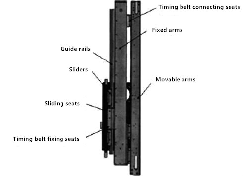
Figure 2 The structure diagram of the first and second arm components
Partial structural design of the beam
Parts of the beam structure is shown in the Figure 3. It can be seen from the Figure 3 that the beam has a thin-walled hollow structure and is made by casted gray cast iron, which has high strength and light weight. The horizontal sliding seat is made of carbon structural steel with better rigidity. The guide rail and slider also use ball linear guide rails, and the bottom of the beam is fixed on the base. The horizontal sliding seat is installed on the guide rail slider, and the sliding seat is equipped with servo motors, reducers, pulleys, idlers and other parts. Driven by the servo motor, the sliding seat is driven by the timing belt to complete the horizontal movement.
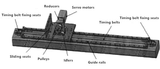
Figure 3 The structure diagram of the beam
The structure of the second arm is a double-speed type, and the slider connected to the cantilever guide rail is mounted on the sliding seat. This structure is more conducive to saving space. Its working principle is that the sliding seat is fixed and the fixed arm moves up and down mainly driven by a servo motor; the fixed arm is equipped with a timing belt; the timing belt fixing seat is connected to the sliding seat, and the timing belt connection seat is fixed on the movable arm; the slider of the movable arm can move along the guide rail on the fixed arm; when the fixed arm moves, the timing belt transmits the movement to the movable arm, and the moving speed of the movable arm relative to the sliding seat is twice the speed of the fixed arm. The double-section telescopic structure can reduce the overall height of the injection robotic arm and reduce the working time at the same time.
Figure 2 The structure diagram of the first and second arm components
Partial structural design of the beam
Parts of the beam structure is shown in the Figure 3. It can be seen from the Figure 3 that the beam has a thin-walled hollow structure and is made by casted gray cast iron, which has high strength and light weight. The horizontal sliding seat is made of carbon structural steel with better rigidity. The guide rail and slider also use ball linear guide rails, and the bottom of the beam is fixed on the base. The horizontal sliding seat is installed on the guide rail slider, and the sliding seat is equipped with servo motors, reducers, pulleys, idlers and other parts. Driven by the servo motor, the sliding seat is driven by the timing belt to complete the horizontal movement.
Figure 3 The structure diagram of the beam
